Bipolar Junction Transistor (BJT) Overview, Operating Modes, Switches, and Relay Driver Circuits
Supplies Needed (if you’d like to build the following circuits)
- Minimum breadboarding equipment (see here)
- (1) General purpose LED
- (1) 1/4 watt resistor kit (see here)
- (1) 2n3904 general purpose NPN transistor
- (1) 2n3906 general purpose PNP transistor
- (1) 1n1007 diode or equivalent
- (1) High-powered LED – White
- (1) 12 v, 365 ohm Relay, RT334012
BJT Overview
The BJT or bipolar junction transistor is a 3-terminal semiconductor device that can be used amplify current. The three terminals are the emitter, the base, and collector. The BJT is primarily used in three operating modes: Cutoff, Active, and saturation. There are two types of BJT’s – the NPN and PNP.
BJT Types
Bipolar Junction Transistors come in two types: NPN, and PNP.
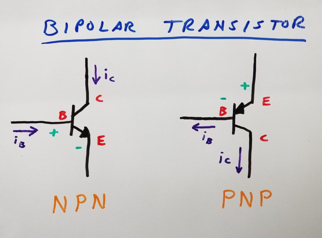
In order to conduct, NPN transistors require that the base is sufficiently more positive with respect to the emitter. PNP transistors require that the base be negative with respect to the emitter.
Configuration
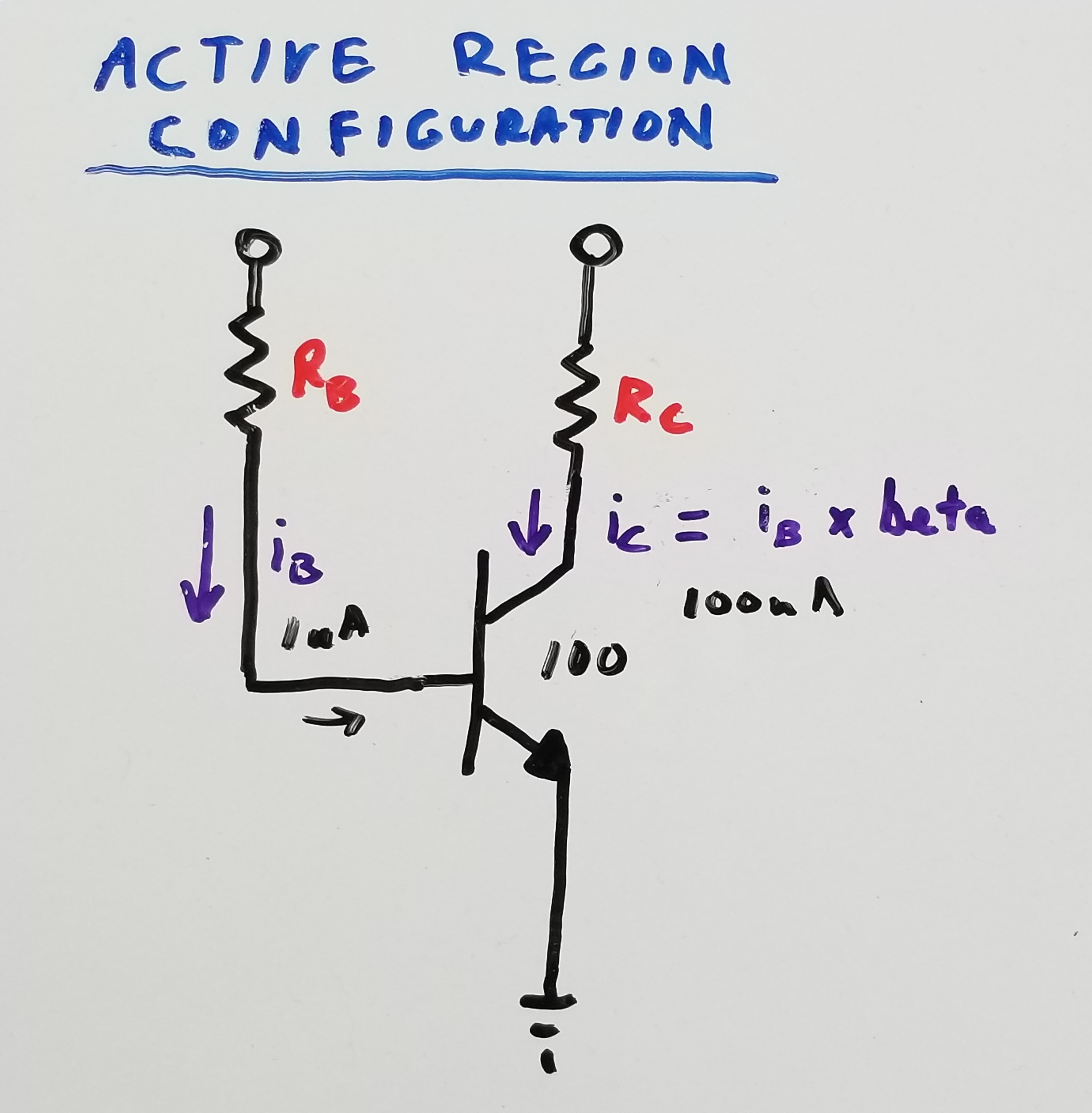
Transistors amplify the current flowing into the base by a factor that is determined by its gain (also referred to as beta or hFE). The amplified current flows through the collector. The emitter current is the base current plus the collector current. This is illustrated in the following diagram.
Operating Regions
There are three primary operation regions of Bipolar Junction Transistors.
- Cutoff
- Active
- Saturation
Cutoff Region
In the cutoff region, the transistor does not conduct between the collector and emitter. As a switch, it is considered to be turned “off”. The voltage across the transistor (between the collector and emitter) is at its maximum value (approximately equal to the supply voltage or Vcc).
Active Region
In the active region, the transistor is considered to be an amplifier. The gain of the transistor in this region will dictate the collector current as a multiple of the base current. It is the linear operating region of the transistor. There is also a “reverse-active” region, which is rarely used and won’t be discussed.
Saturation Region
In the saturation region, the transistor fully conducts between the collector and emitter. As a switch, it is considered to be turned “on”. The voltage across the transistor (between the collector and emitter) is at its minimum value (approximately 0 volts).
Illustration of Operating Regions
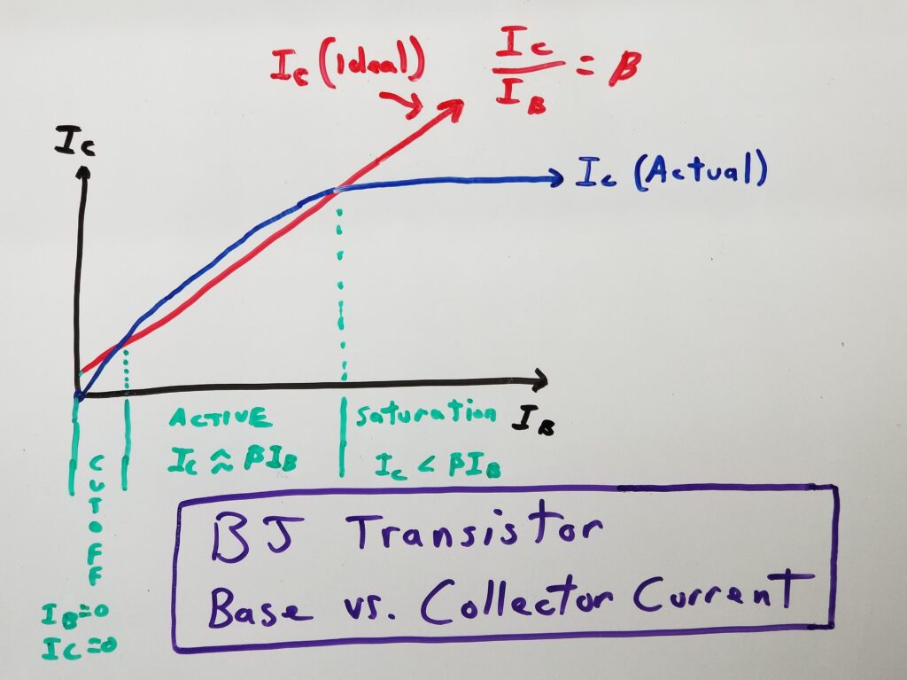
The following graph shows how the collector current of an NPN transistor is related to base current.
There are several important things to note about this graph.
- The X axis of the graph is Ib (base current) and the Y axis Ic (collector current).
- The red line is the ideal plot for Ic as Ib increases. The function for this ideal plot is (Ic/Ib) x beta, where beta is the gain of the transistor (typically 200 for a 2n3904 transistor).
- The blue line plots the actual Ic with respect to Ib.
- The areas in green show the three delineated operating regions of the transistor.
The plot can be described as follows:
- Cutoff – When the Ib is zero, Ic is also zero. This correlates to the cutoff region where the transistor can be considered a switch in the “off” state. The voltage across the transistor (Vce) is also at its maximum.
- Active – As the Ib increases, Ic starts to increase at a rate equal to (Ic/Ib) x beta. The blue plot line roughly follows the ideal red plot line’s slope. This represents the “active” or linear region. The transistor is now acting as an amplifier.
- Saturation – Once Ib increases to a certain point, further increases in Ib result in little to no increases in Ic. Notice that the blue Ic plot line no longer follows the red ideal plot line’s slope. In fact, it reaches a plateau. This represents the saturation region, where Ic < (beta x Ib). The transistor is not acting as a switch in the “closed” state. The voltage across the transistor is also at its minimum (almost zero volts).
BJT Switch Circuit Design
Transistor Selection
There are some primary criteria that you’ll want to consider.
- Collector Current – Ic (max) – Select a transistor with a sufficient collector current rating to handle that of the load at room temperature. Since most BJTs are inexpensive, It is best to choose one that can handle at least twice the required current. Since the transistor’s specification should be derated with temperature, it is best to use one that can handle up to three times the current – when used in a moderately hotter environment.
- Power Dissipation – Pd (max) – When using a transistor as a switch, it is unlikely that power dissipation will be much of a concern – since there should be no voltage drop across the transistor at the same time current flows through it. Generally, if you are meeting the criteria above for collector current, you should be fine with power dissipation for transistor switching applications.
- Collector to Emitter Voltage – Vce (max) should be higher than your supply voltage. In fact, the supply voltage should be no more than 75% of the rated Vce (max).
Base Resistor Calculation
Using a transistor as a switch requires that it be configured to operated in either its cutoff or saturation modes. In the cutoff mode, simply deny the transistor of any base current. To do this, simply set the base voltage to 0 volts.
Saturation mode requires a few simple steps:
- Determine collector or load current.
- Divide the collector current by the transistor’s gain or beta. This gives you the base current needed to put the transistor into its linear active mode.
- Multiply the above calculated base current by 5 in order to drive the transistor into saturation.
- Determine the needed base resistor value by dividing the base switching voltage by the current found in step 3.
Example BJT Switch Design
Constraints
You’re tasked with lighting a 100mA high-powered white LED with a microcontroller and have the following constraints to work with.
- The microcontroller port outputs 5V maximum
- The microcontroller port has a maximum current sourcing capability of 25mA
- The available supply voltage for the LED is 12V
- The LED has a forward voltage drop of 3V
Approach
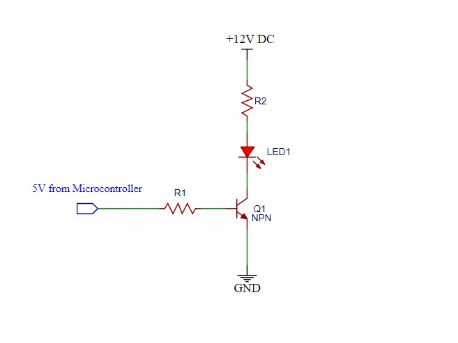
The microcontroller does not have enough current sourcing capability to drive the LED. This is because the current requirement is 100mA and the port can only source 25mA. It is also not good practice to max out your microcontroller’s output port current as the cumulative effect of multiple ports can exceed the microcontroller’s power dissipation rating. Thus you will utilize a transistor to “switch” the LED on and off with minimal current supplied by the microcontroller. To accomplish this, the transistor will be used in two of its three possible operating modes – cutoff and saturation.
The schematic diagram for such a configuration will be as follows:
Current and resistor value calculations
Let’s calculate the proper values of R1 and R2 using the following steps.
- Find voltage drop across R2. When a transistor is used as a switch, we’ll assume that the voltage across it is close to 0 volts. The LED has a voltage drop of 3 volts. If we subtract the 3 volts from our voltage supply of 12 volts, we have 9 volts. This is the voltage across R2.
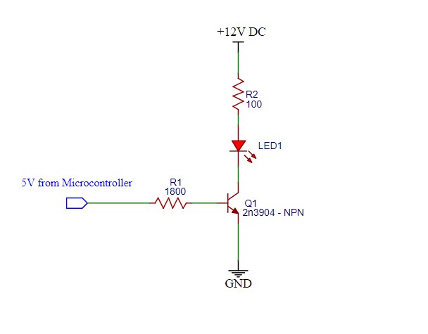
- Find the value of R2 for 100mA of current flow. The resistance value of R2 will be (per Ohm’s law), R=V/I. Thus R= 9 volts / 100mA = 90 ohms. A close standard value is 100 ohms. Note that the power this resistor will need to dissipate is 100 x I x I = 1 watt. Thus you won’t want to use a standard 1/4 watt resistor for this exercise. You can, however, use (4) 1/4 watt resistors in parallel (for prototyping purposes). To create a 1 watt resistor 4 such resistors, you can use a standard value of 390 ohms. (4) 390 ohm resistors in parallel is equal to a 97.5 ohms – which is certainly close enough for a prototype.
- Find the base current that will put transistor Q1 into saturation. This is one of the most important parts of this exercise. Assuming a transistor “beta” or gain of around 200, we can first calculate the needed current to cause 100mA to flow through Q1’s collector and thus the LED. This current will be Ic/beta or 100mA/200 or 0.5mA. Now – although this current will provide for 100mA at Ic, the transistor is between its active and saturation modes. To “drive” it sufficiently into saturation, you’ll want to multiply that current by a factor of between 2-5. I usually use 5 as a rule of thumb. So using an overdrive factor of 5 will give us 2.5 mA. This is well below what the microcontroller’s current sourcing capability is. Note that the higher that factor is, the more base current you’ll have. A lower factor will save some energy, but only a few % as compared to the collector current.
- Find the appropriate value of R1. This is quite easy. Now that you know your base current, you only need to use Ohm’s law to do the rest. The microcontroller outputs either 0 volts or 5 volts. You need a positive voltage at the base with respect to the emitter – for an NPN transistor to conduct. Thus we’ll use 5 volts for “on” and 0 volts for “off”. The voltage between the base and emitter of an NPN transistor when conducting, is 0.7v. This leaves 4.3 volts across R2. You simply now divide the 4.3 volts by the base current of 2.5mA to find your resistor value. This is 4.3 / .0025 = 1720 ohms. The closest standard value is 1800 ohms. You have some leeway for the base resistor, since you are already well beyond the minimum current needed to push Q1 into saturation. A simpler way to select a base resistor is to use rule of thumb of Ib = (Ic/beta) x 5, which is essentially what you did in the analysis above.
- Select an appropriate transistor. The 2n3904 general purpose transistor will meet the criteria for this exercise. It is a 60v, 200mA component with a beta of around 200.
Final Schematic
Below is the final schematic with the calculated resistor values and selected transistor.
Breadboarded Circuit
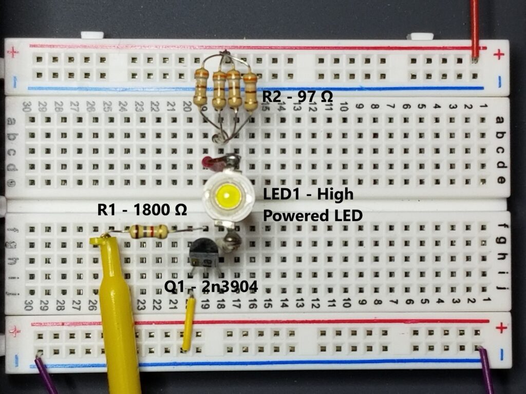
Below is a picture of the breadboarded circuit, with (4) 390Ω resistors in parallel with the equivalent resistance of 97 ohms. The resistor bank needs to dissipate 1 watt of power – hence the (4) 1/4 watt resistors in parallel.
Circuit in Operation
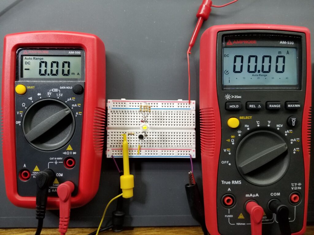
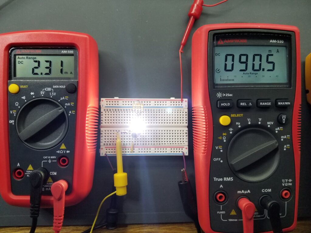
The circuit in action. The first picture is with the transistor in cutoff (off) mode and the LED off. The voltage on the left side of R1 is zero volts. The second picture is with the transistor in saturation (on) mode and the LED on. The voltage at the left of R1 is 5 volts, which simulates the output of a microcontroller port. The currents and voltages are fairly close to those calculated. The base current is on the left and collector/LED current on the right. Be careful not to touch the resistors as they are operating at their power dissipation limit and will be very hot.
The Relay Driver Circuit
The Relay Coil as the Circuit Load
Transistors are commonly used to drive DC relay coils. A DC relay coil has resistance. It is this resistance that is used to calculate the transistor’s collector current and thus the base current and base resistor value. Although the relay coil is also an inductor, this is largely irrelevant in the circuit. There is what’s known as a “transient response” when the relay is energized and de-energized. Since inductors resist changes in current, the inductive component actually causes the collector current to slowly “ramp up”. There is no “inrush” current. The main consideration of the relay coil’s transient response is that when de-energized, a negative voltage spike will appear across the coil. This spike can damage nearby components – including the driver transistor. To mitigate this, a “flyback diode” is placed in parallel with the coil. This will “clamp” any such voltage spike. Other than this simple transient consideration, you will treat the relay coil as just a resistor. It is this resistance value that drives the circuit design and calculations.
Basic Relay Driver
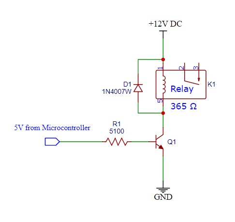
A basic relay driver circuit will be configured as a BJT switch as described in the previous section. This configuration is also known as a “low side switch”. The transistor will be driven by a microcontroller with an output voltage of 5 volts. The coil voltage for the example design is 12 volts. The coil resistance is 365 ohms. The coil current, and thus the transistor collector current is V/R or 12/365 = 33mA. A general purpose transistor NPN such as the 2n3904 can be used as it has a Vce(max) (maximum collector to emitter voltage) of 60v and a maximum collector current of 200mA. It also has a beta (or gain) of about 200.
You can now calculate the transistor’s base current by using the rule of thumb (established in the previous section) of (Ic/beta x 5). This gives us (0.033/200) x 5 = 0.825 mA (or 826uA). The voltage across R1 when the microcontroller is outputting 5 volts, will be that 5 volts minus the voltage at the transistor’s base (Vbe), which is 0.7 volts when conducting. This yields a 4.3 volt difference across R1. The value of R1 will thus be R=V/I = 4.3v / 0.000825 A = 5212 ohms. The closest standard value is 5100 ohms. Below is the schematic base on these calculations:
Breadboarded Single Stage Relay Circuit
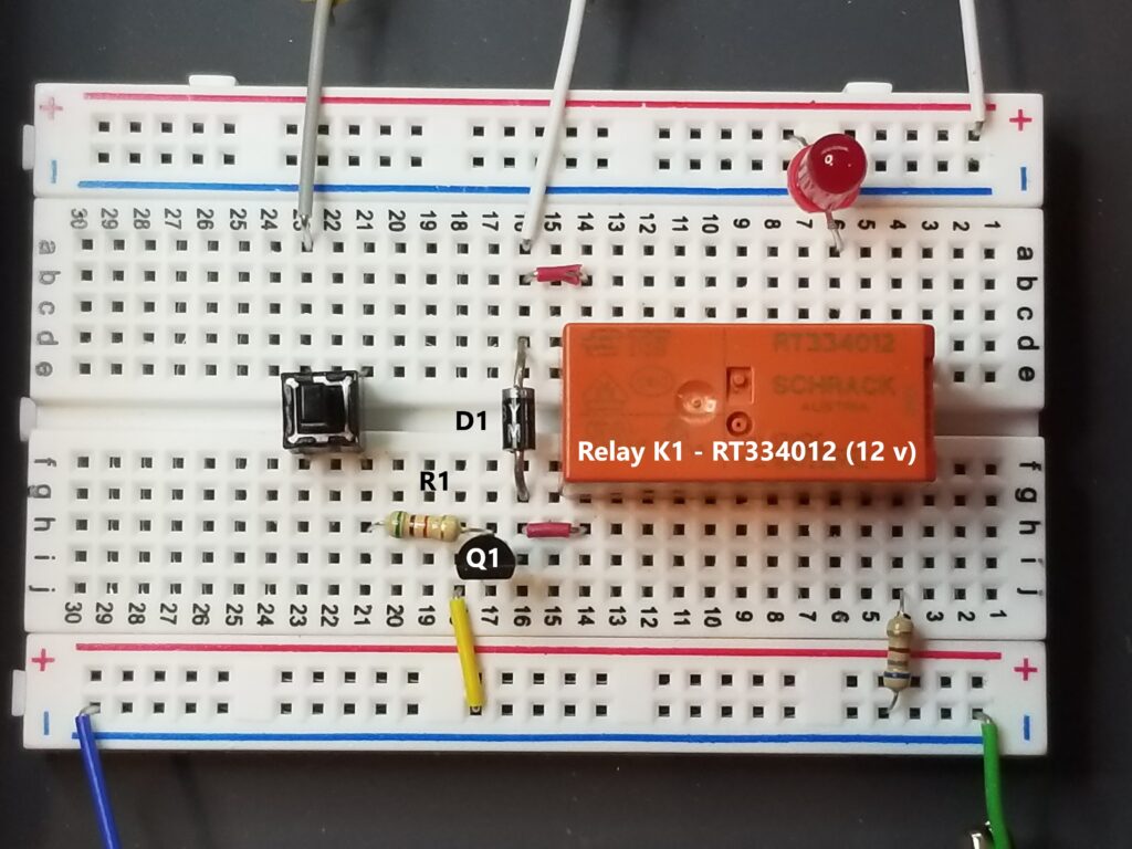
Below is a picture of the populated breadboard with the labeled components. On this breadboard, there is an option LED and current limiting resistor connected to the relay contacts to illustrate the relay’s “on” or “off” state. Also, there is an optional pushbutton switch to simulate the +5 v input from the microcontroller.
Note that you can use a different 12 v relay, but will want to recalculate the transistor’s base resistor if the coil resistance is more than 15% off from the specified 365 Ω relay. This is because the relay’s coil resistance dictates the transistor’s collector current and thus the needed base current to sustain that collector current.
Single Stage Operation
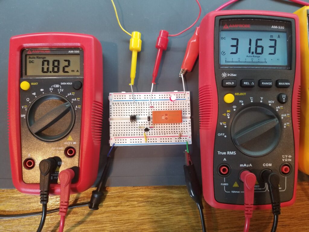
Below is a picture of the breadboard with ammeters measuring current at both the base and collector of the driver transistor. Note that small amount of current at the base (left), 0.82 milliamps, needed to drive the transistor’s collector (and thus relay coil) current (on the right), 31.6 milliamps. This is a total gain (or current amplification) of 38.5.
Dual Stage Relay Driver
This circuit uses a PNP “high-side switch”, driven by “low-side” NPN pre-driver. This circuit has several advantages. The relay will share a common ground with the rest of the circuit – and the microcontroller is more well distanced from the higher-current relay. If the flyback diode were to short out (and they do) on the single-stage version, it could be subject the output port of the microcontroller to a 12 v potential – which most microcontrollers are unable to tolerate. If Q2 were to “short out” and apply a 12 v and pass the full 12 v potential down into the circuit and to the top of R2, it would be inconsequential to Q1 and the microcontroller, since 12 v already regularly sits at the top of R2 by design.
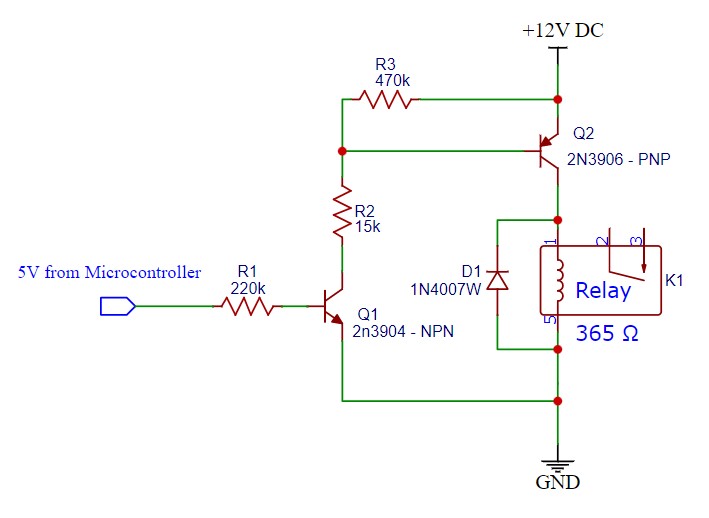
Dual Stage Design
Designing the dual stage circuit follows the same general guidelines as the for the single-stage circuit. Here are the steps:
- Relay current = Q2 collector current (Ic)= 12v/365Ω = 33mA.
- Needed base current for full saturation = (Ic / beta (200) ) x 5 = (.033 / 200) x 5 = .825mA (825uA)
- Q2 base resistor value R2 = (12 v – 0.7 v (Q2 Vbe) ) / .000825A = 13.7k (close standard value = 15k)
- Q1 collector current (Ic) is the same as Q1 base current = .825mA
- Q1 base current = Q1 (Ic / beta (200)) x 5) = .021mA or 21uA
- Q1 base resistor = (5 v – 0.7 v) / .021mA = 205k (close standard value = 220k)
- Q2 pull-up resistor used to switch off Q2 when Q1 is off. 470k will pull Q2 base high without no significant affect on circuit’s operational current.
Breadboarded Dual Stage Relay Circuit
Below is a picture of the populated dual stage breadboard with the labeled components. Like the single stage breadboard, there is an option LED and current limiting resistor connected to the relay contacts to illustrate the relay’s “on” or “off” state. Also, there is an optional pushbutton switch to simulate the +5 v input from the microcontroller.
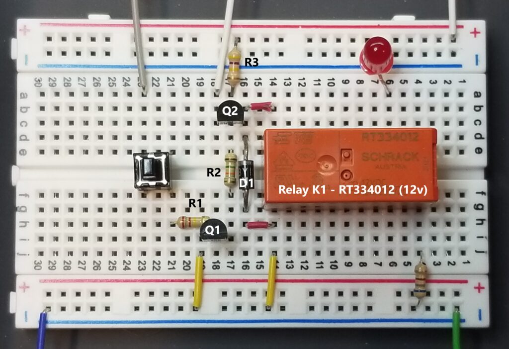
Dual Stage Operation
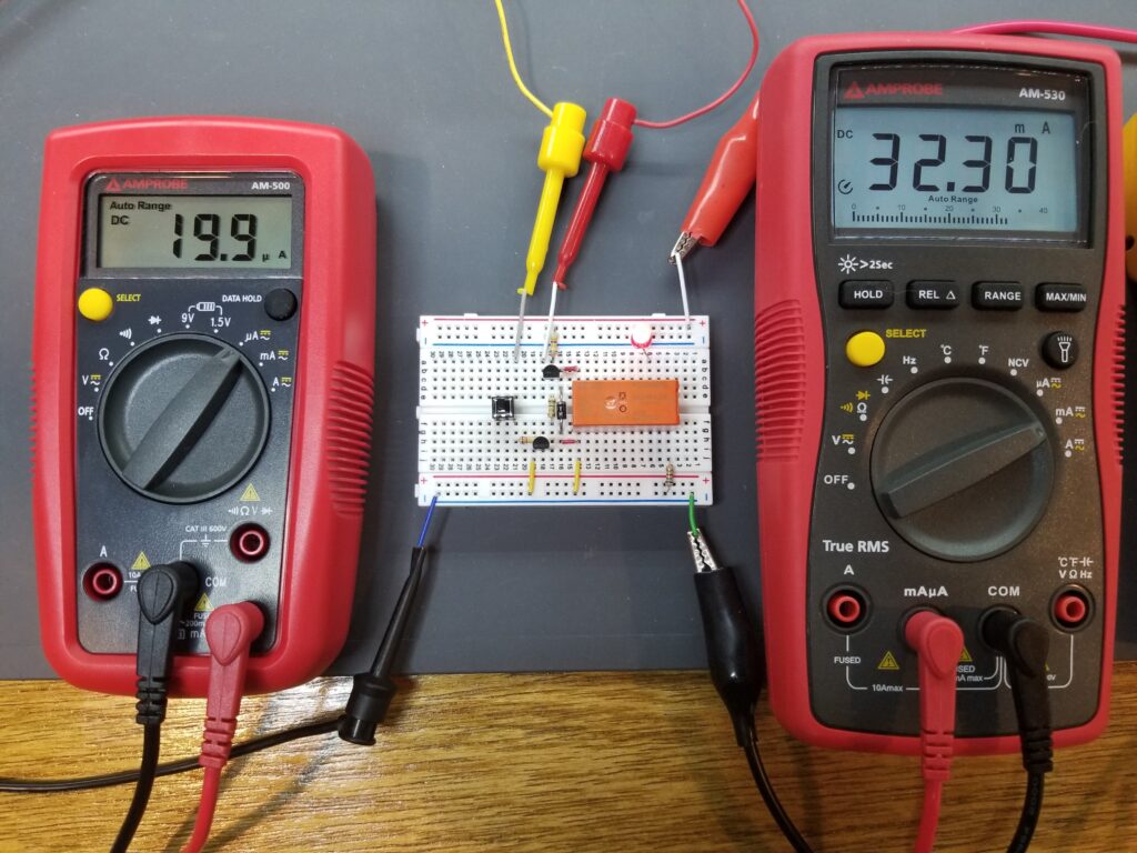
Below is a picture of the breadboard with two ammeters. The one on the left is measuring the base current at Q1 and the one on the right is measuring the collector current at Q2. Note the extremely small amount of needed current coming from microcontroller (attached to the base of Q1),19.9 microamps, that will ultimately switch Q2 on and supply the relatively large amount of current at it’s collector (and relay coil), 32.3 milliamps. This is a total gain (or current amplification) of 1623. This way, you can energize an oven bake or broil element with the miniscule output of a microcontroller. In fact, given that the relay has a 30 amp contact rating – this means that you can control 30 amps with 19.9 microamps – an effective circuit gain (or current amplification) of 1.5 million.
Please see the matching video for this article on our Youtube Channel below.
For a better experience building breadboarded circuits, please see our page detailing the minimum recommended lab equipment for your electronics bench. Also, don’t forget to review the recommended safety tips to follow when building and testing breadboarded circuits
Finally, for other interesting breadboarded circuits please visit the home page here or our YouTube channel here. SM
We are a participant in the Amazon Services LLC Associates Program, an affiliate advertising program designed to provide a means for us to earn fees by linking to Amazon.com and affiliated sites.
