Considerations when Lighting an LED
There are two primary considerations for lighting an LED.
- LED Polarity
- LED current
LED Polarity
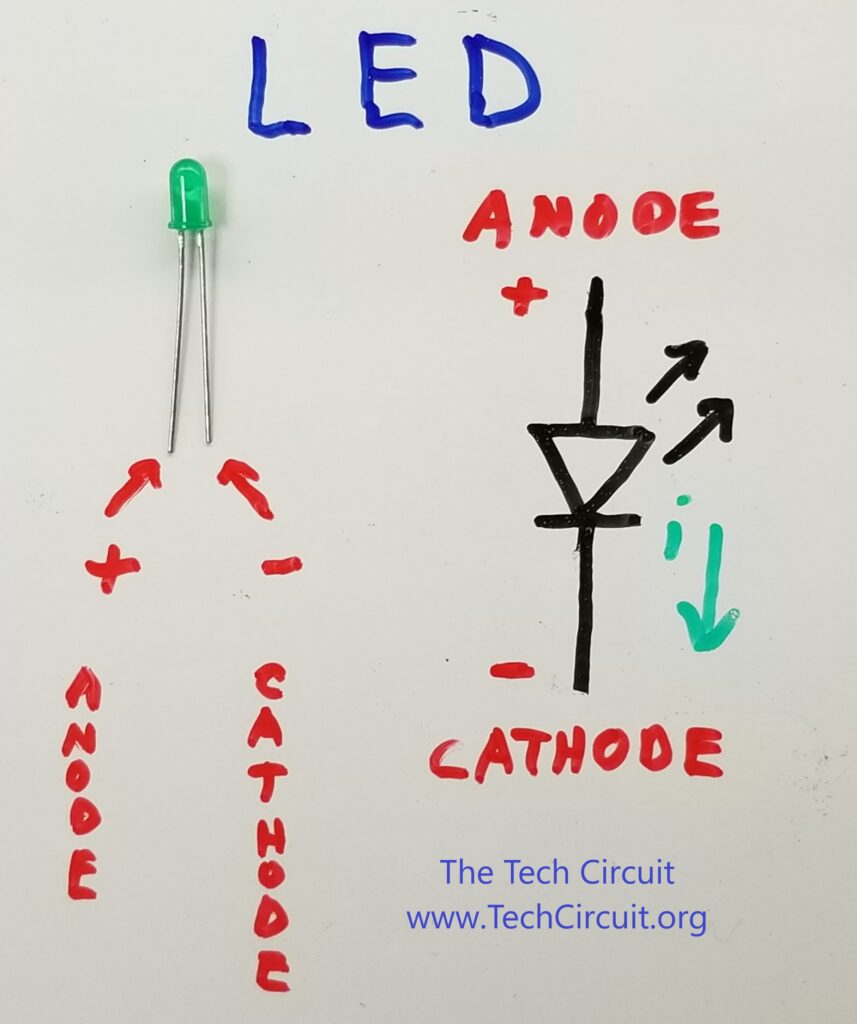
LEDs are diodes – and diodes only pass current in one direction. Therefore, if you hook an LED up backwards, it won’t light, and can even be damaged. Below is the schematic symbol for an LED. Note the direction of the current. By the way, all projects at BreadBoardCircuits.com use conventional current flow, which is from positive to negative.
An easy way to remember the direction of the current flow through a diode (or LED) is that the direction of the arrow points in the direction of that current flow. The pointed side of the LED is the negative (or cathode) side, and the other side is the positive (or anode) side. On the actual LED, the long lead is the Anode (+) and the shorter lead is the Cathode (-). Refer to the picture below. Note that connecting an backwards can potentially damage it.
LED Current
LEDs can only handle so much current. In fact, most standard red and green LEDs have a maximum current of 20mA (.02A). A good current range to use is between 10mA (0.01A) and 15mA (0.015A) of current. This information can be found on the LED’s datasheet.
Parts List
- Breadboard, Power Supply (or 9V battery) and associated equipment (click here for more info)
- (1) Standard red or green LED
- (1) 680 ohm 1/4 watt resistor (see resistor kit here)
Circuit Schematic
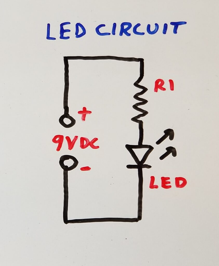
Below is the schematic that shows the basic configuration for lighting an LED. Note that the pointed side of the LED points toward the negative (or ground) side of the battery or power supply. The current limiting resistor is connected between the positive side of the battery or power supply and the positive side of the LED.
Current Limiting Resistor Calculation
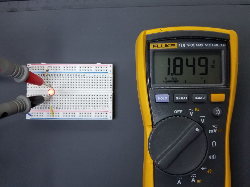
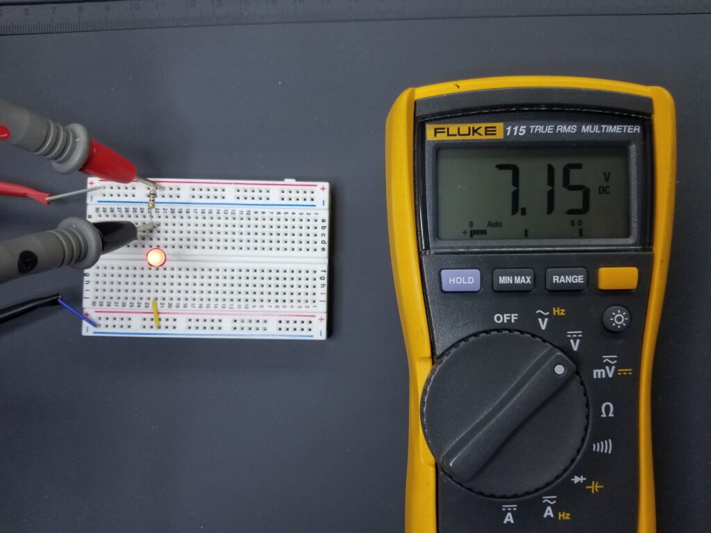
Given that the LED circuit will be configured as above, we can calculate the needed resistor value using simple Ohm’s law. The LED will drop 2V of the 9V supply – leaving 7 volts across the resistor. Ohm’s law states that R=V/I. Thus the value of R for 10mA is 7/.01 = 700 ohms. Therefore, the value for 15mA is would be 7/.015 = 467 ohms. So to light the LED, you could safely use a standard resistor value of between 467-700 ohms. We’ll pick a standard value of 680 ohms.
Picture of the Breadboard and 9V
Battery Connection
Voltage and Current Measurements
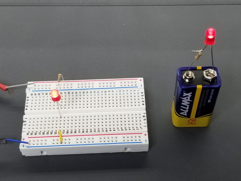
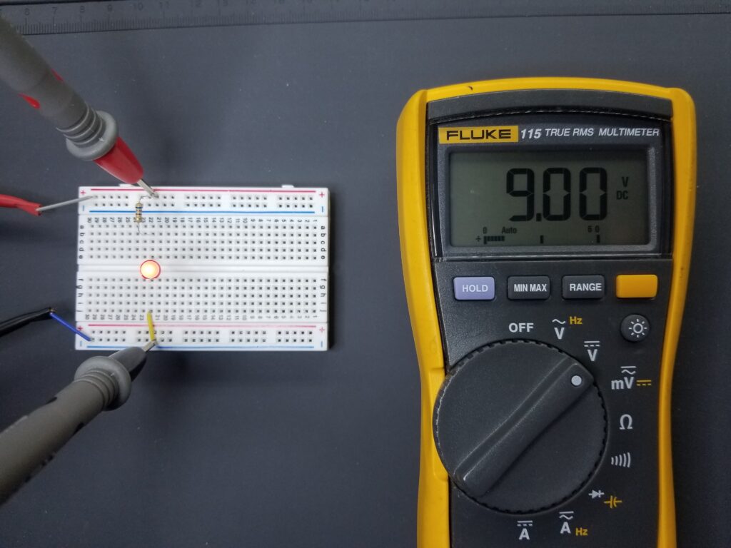
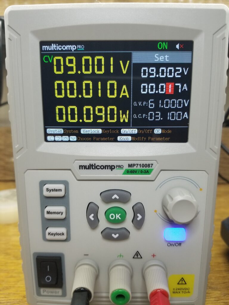
Below are pictures of the LED circuit connected to a Breadboard, as well as a 9V battery. The first image is that of the voltage supply. The second one is the voltage across the LED. Next, the third picture is the remaining voltage across the resistor. Finally, the picture is that of the Multicomp Pro power supply display showing a current draw of 10mA. All measurements come very close to calculations.
Conclusion
Lighting a standard LED is very simple, given that a few rules are followed.
- Keep the current at or below 15mA using a current limiting resistor.
- Orient the LED in the right direction.
Please see the matching video for this article on our Youtube Channel below.
For a better experience building breadboarded circuits, please see our page detailing the minimum recommended lab equipment for your electronics bench. Also, don’t forget to review the recommended safety procedures to follow when building and testing breadboarded circuits.
Finally, for other interesting breadboarded circuits please visit the home page here or our YouTube channel here. SM
We are a participant in the Amazon Services LLC Associates Program, an affiliate advertising program designed to provide a means for us to earn fees by linking to Amazon.com and affiliated sites.
