What is an Op Amp Oscillator?
An op amp oscillator is an amplifier that uses feedback and resulting hysteresis to cause oscillation. The circuit only requires five components. The output will be a square wave – the frequency of which is determined by a resistor and capacitor. This circuit is configured for 1kHz. The hysteresis() is determined by the value of two additional resistors.
Parts Needed
- Minimum breadboarding supplies (CLICK HERE FOR RECOMMENDED SUPPLIES)
- RC4558 dual op amp (CLICK HERE FOR RECOMMENDED ANALOG IC KIT)
- (1) 100k potentiometer (CLICK HERE FOR RECOMMENDED POTENTIOMETER KIT)
- (4) 10k ohm, 1/4 watt resistors
- (1) 10 ohm, 1/4 watt resistor
- (2) 0.1 uF, 25v ceramic capacitor
- (1) 10 uF, 25v electrolytic capacitor
Schematic Diagram
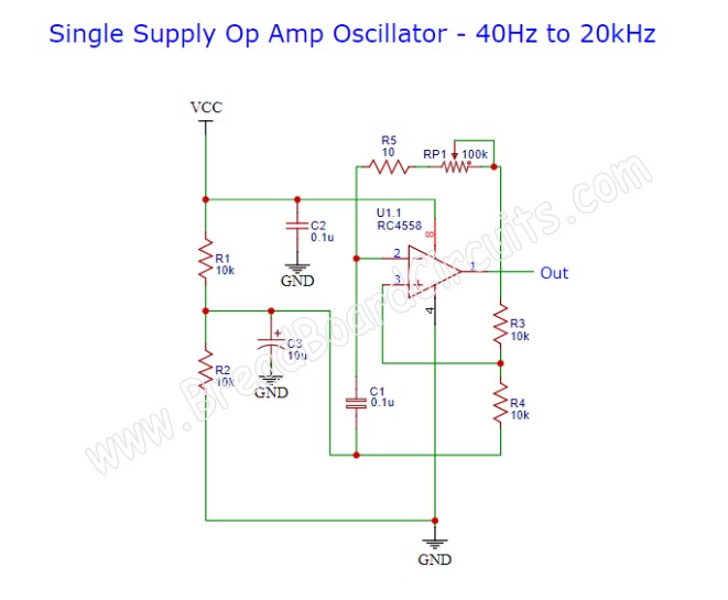
Below is the schematic diagram of a single supply op amp oscillator that is supplied by 9vdc.

Breadboarded Circuit
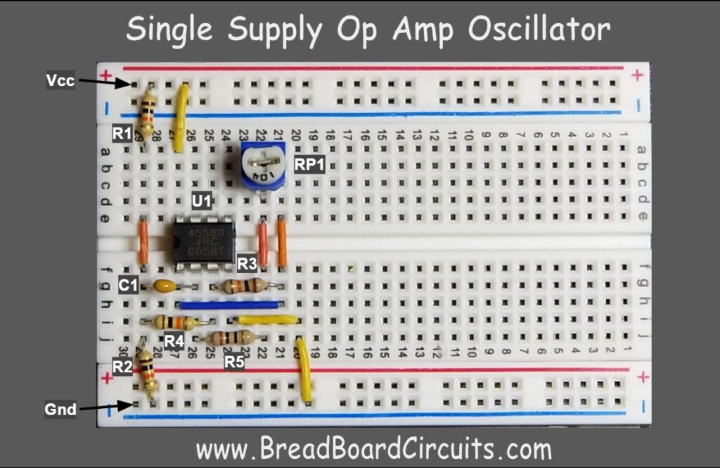
Below is a picture of the breadboarded circuit along with the schematic references. Build exactly as shown.

Theory of Operation
In order for oscillation to occur, the op-amp is set up as a comparator with hysteresis. This is also known as a Schmitt trigger. This comparator changes states when one of the inputs crosses a voltage level threshold. The threshold level for a high output is different than the threshold voltage for a low output. This is hysteresis – a mechanism made possible by the feedback voltage divider network. Feedback from the output causes the reference voltage level to change when when the output toggles. This means that a different voltage level threshold will have to be crossed to change to the opposite state. The timing in which this occurs is based on the series resistors and capacitor. The time constant associated with their values dictates how long it takes for the feedback to cross the switching threshold. This in-turn, determines the oscillation frequency. Since the feedback resistors are equal in value, the oscillation frequency is 1/(2.2RC) where R = (R5 + RP1) and C = C1 in the above schematic.
There is an additional operational amplifier in the RC4558 package. This can be used for other purposes such as:
- Converting the square wave into either a triangular wave (integrator)
- Converting to a sine wave using filters as shown in another project on this website
- To drive an emitter follower if you need a low impedance output
- Amplifying, reducing, or level-shifting the rectangular wave output
Output Waveform
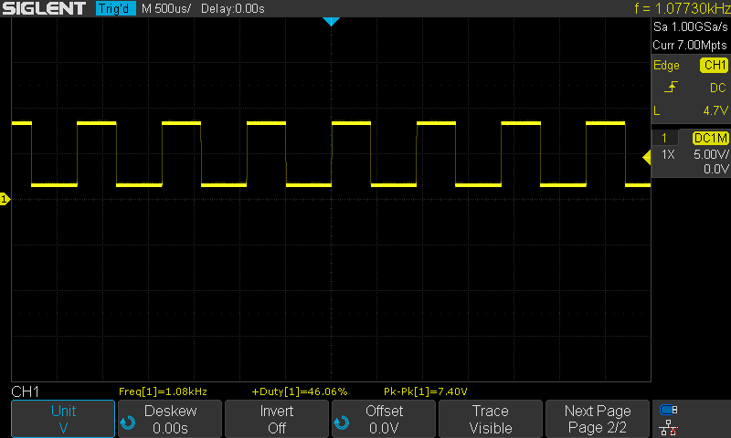
The output waveform on the oscilloscope is shown below. It is a 1kHz rectangular wave with a fairly clean rise and fall time. This is because the RC4558 has a relatively high slew rate of 1.7v/uS as compared to about 0.3v/uS for an LM358. The magnitude and offset is constrained by the op-amp’s output swing. You can see that the waveform has a DC offset of about 1v and maxes out at 7.4v p-p with a 9v supply. (CLICK HERE FOR LINK TO OSCILLOSCOPE)

Summary
A simple Square wave oscillator can be easily constructed using an op amp that is configured as a comparator with hysteresis. The frequency of the oscillation is determined by one resistor and a capacitor. This oscillator circuit can be used as a clock frequency for many projects or for any circuit that requires a square wave.
For a better experience building breadboarded circuits, please see our page detailing the minimum recommended lab equipment for your electronics bench. Also, don’t forget to review the recommended safety procedures to follow when building and testing breadboarded circuits.
Finally, for other interesting breadboarded circuits please visit the home page here or our YouTube channel here. SM
We are a participant in the Amazon Services LLC Associates Program, an affiliate advertising program designed to provide a means for us to earn fees by linking to Amazon.com and affiliated sites.
