Build a Four-Transistor PWM Generator
In a previous project, we designed and breadboarded a 1KHz multivibrator circuit consisting of four transistors. With a simple modification, that circuit will be able to produce a clean and adjustable Pulse Width Modulated output with a duty cycle of between 15% and 85%. This PWM Generator can easily be built on a breadboard.
Before building a breadboard, please review our safety recommendations page.
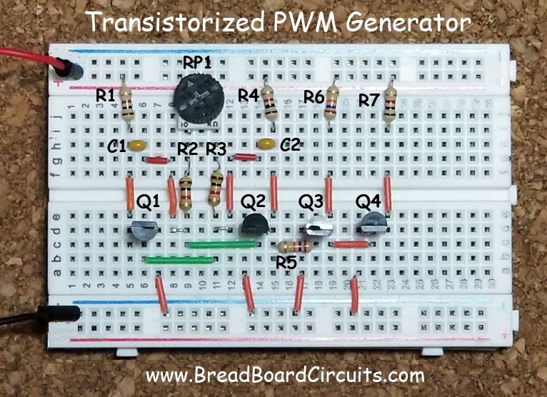
A picture of the PWM generator circuit is shown below along with schematic references. Schematic is shown below in this article.

Supplies Needed
Supplies needed for this project:
- Minimum breadboard equipment (see here)
- (1) 10k ohm potentiometer
- (5) 1k ohm 1/4 watt resistors
- (2) 27k ohm 1/4 watt resistors
- (2) 0.1uF 16v Mylar capacitors
- (4) 2n3904 transistors
Construct the circuit exactly as shown on the breadboard, observing the orientation of the 2n3904 NPN transistors. Notice that Q1 is facing backward, while Q2, Q3, and Q4 are facing forward. If you already constructed the mulitvibrator in the improved astable multivibrator project, you can easily modify it for this project.
The 2n3904 NPN Transistor
Below is both the pinout (with the transistor facing forward) and symbol for the 2n3094 transistor. “E” stands for Emitter, “B” stands for Base, and “C” stands for Collector.

What is PWM (pulse width modulation)?
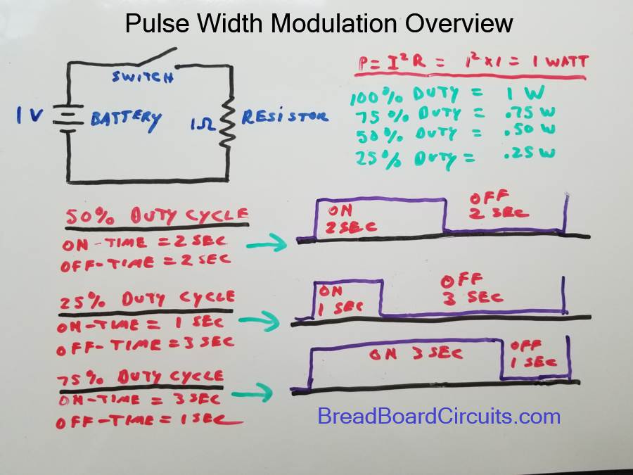
PWM is a method of controlling the average power applied by an electrical signal by varying the on and off times of that signal. It is most often used with a DC voltage source and is measured in percent of duty cycle. The duty cycle is simply the (on time) / (on time + off time). For example, a battery has a constant DC output and thus has a 100% duty cycle. Simple enough. If you were to connect that battery to a resistor through a switch, you can control the percentage of time that current is flowing through that resistor. For simplicity, suppose the battery was one volt and the resistor one ohm. You turn the switch on for one second and then off for one second. You repeated this indefinitely. The duty cycle of the voltage applied to the resistor would then be 50%. The power that resistor absorbs would also be 50%. This proportionally holds true for any duty cycle you subject the circuit to. This is illustrated in the picture below.

What primarily separates PWM power delivery from using a rheostat or potentiometer to control power to a load, is that the PWM still applies full power when the signal is “on”. Thus the “instantaneous power” is 100% during that time. This means that LED’s will instantaneously operate in their specified range and wavelength, and DC motors will have full torque, yet still have variable power – because you are varying the average amount of time that the instantaneous power is applied. Also PWM is much less effected by changes in load resistance because PWM drivers typically have a very low impedance output – whereas rheostats/potentiometers inherently have a higher impedance – which is bad. Practical applications of PWM are most often implemented using electronic switches such as transistors. Such driver circuits are commonly used to control the speed of brushed DC motors such as fans and for dimming LEDs. PWM is far superior than, and has almost completely supplanted, traditional rheostat methods for controlling such loads. For the project described in this article, you will learn to build a 4-transistor PWM controller derived from a simple mulitvibrator circuit described in a previous article.
Schematic of the PWM Generator
The schematic is shown below. Note that it is designed to be powered by 9 volts DC. Attempting to increase the input voltage may exceed the component’s ratings.

Frequency Selection
Early PWM implementations suffered from noise for motor control and “flicker” for LED control because of the low frequency. For this project, we will use a base frequency of between 1 – 2KHz, which is suitable for “non-flicker” LED brightness control. The multivibrator oscillator consists of 2 RC circuits – one for each transistor Q1 and Q2. Each RC circuit takes time (T) to charge enough to flip the base of The time period of the oscillator is equal to The base frequency will be calculated assuming a 50% duty cycle and thus symmetrical circuit charge times. This frequency can be determined by the formula 0.72/(RxC). If we use 6 k ohms for R and 0.1uF for C, we get 0.72/(6000 x 0.0000001) or 1200 Hz. Referring to the schematic, the when the potentiometer is set midway, the oscillator acts as a traditional mulitvibrator circuit with the equivalent of two 6k ohm resistors in the RC circuit. This is because when the pot is set mid-way, the resistance from the base of each transistor to Vcc is 6k ohms. To vary the pulse width though, we’ll need a potentiometer to introduce the needed asymmetry. The potentiometer’s location in the circuit is ideal for creating this asymmetry because as you increase the RC time constant for Q1, you correspondingly decrease that constant for Q2. In doing so, you can have an approximate 15% to 85% duty cycle.
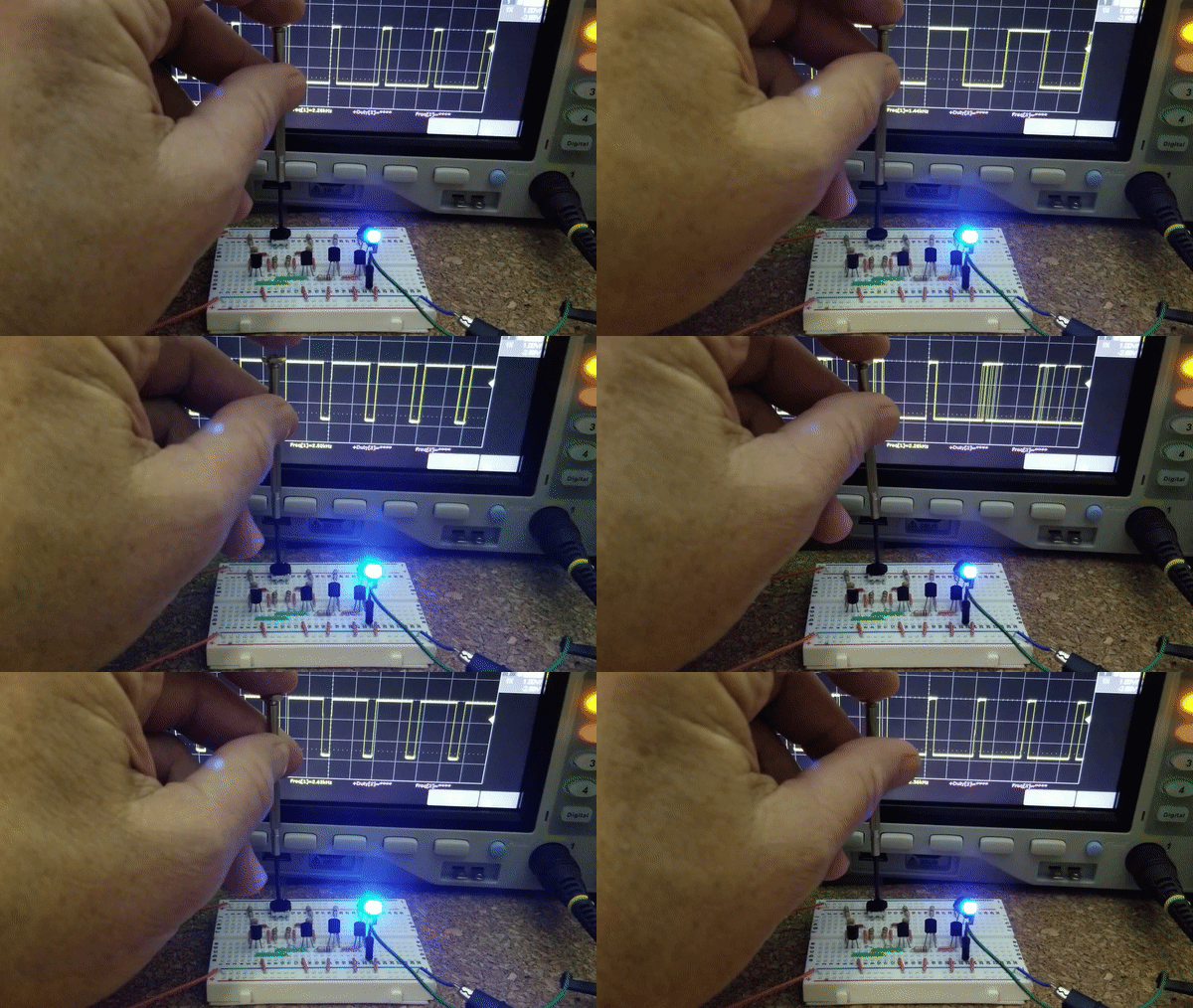
Video of PWM Generator Controlling an LED’s Brightness

Project Video
Conclusion
Pulse width modulation controls the total amount of time per cycle that a signal is high vs. low. In doing so, it can be used to control power to a load in a way that allows that load to operate as specified for the times the signal is “on”. This instantaneous power results in LED’s being dimmable, yet to emit the correct wavelength of light, and DC brushed motors to be speed controllable, yet still have high torque. The circuit in this article is simple and was done with minimal discrete components. The duty cycle range is limited to between 15-85%, yet could be wider with some adjustments and frequency trade-offs.
For a better experience building breadboarded circuits, please see our page detailing the minimum recommended lab equipment for your electronics bench. Also, don’t forget to review the recommended safety procedures to follow when building and testing breadboarded circuits.
Finally, for other interesting breadboarded circuits please visit the home page here or our YouTube channel here. SM
We are a participant in the Amazon Services LLC Associates Program, an affiliate advertising program designed to provide a means for us to earn fees by linking to Amazon.com and affiliated sites.
