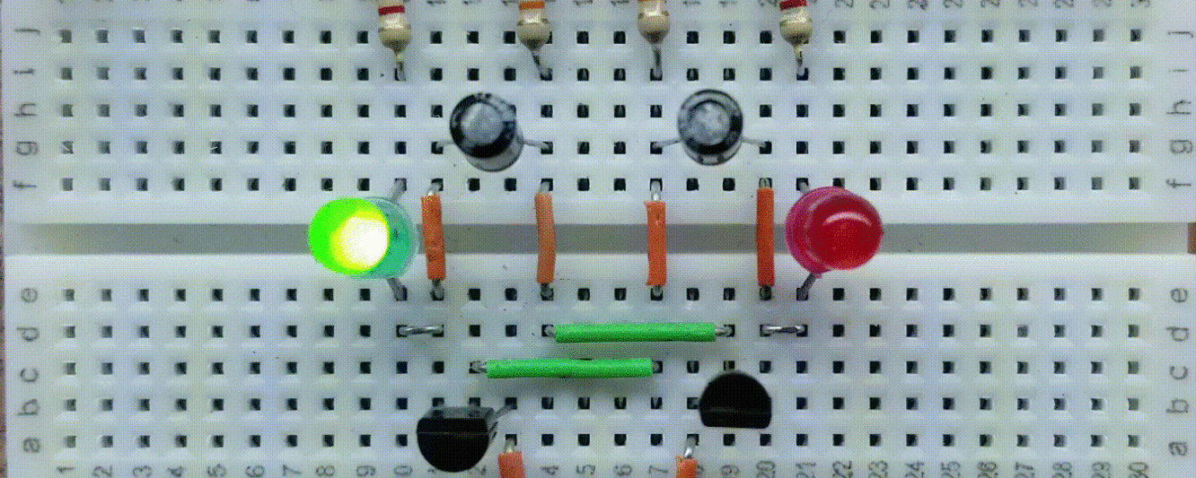
What is a Current Mirror?
A current mirror is a circuit that takes the current through one load and “copies” it through a load on another branch of the circuit. The current mirror also provides a constant current source through that target load.
BJT (Bipolar Junction Transistor) Current Mirror Design
Basic Configuration
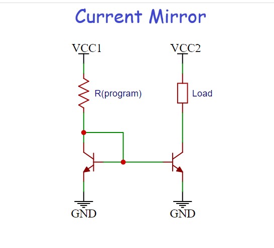
The basic configuration for the BJT current mirror is shown below. It consists of two matched NPN transistors and a “program resistor” used to determine the reference current. Since this is a current mirror, that reference current will also flow through the target load. The program resistor Rprogram is adjusted until the desired amount of current flows through it. The current through the Load is the same as through Rprogram, and is supplied to that load as a constant current. Hence, changes to the load resistance (within design parameters), ideally will not affect the current through that load. The current mirror circuit, as shown, can use two different voltage sources (or supplies), provided that they share the same ground.
Parts Needed
- Minimum breadboarding equipment (see here)
- (4) General purpose LEDs
- (1) 1/4 watt resistor kit (see here)
- (2) Matched 2n3904 general purpose NPN transistors (two transistors that have the same beta and Vbe)
Design
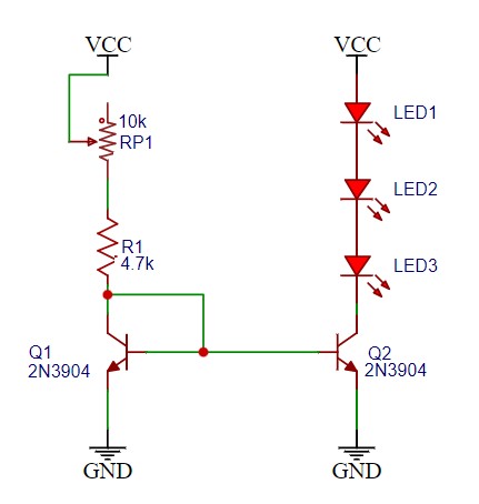
This is the specific design of the BJT current mirror. Adjusting Pot RP1 will give you a mirrored constant current of between 0.75 to 2.50 mA to the target load of series LEDs.
Picture of Breadboard
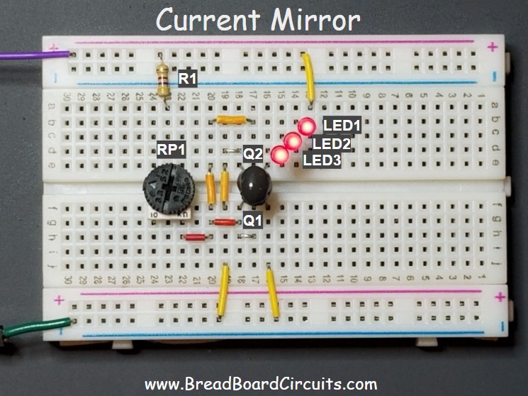
Below is a picture of the breadboard with the components labeled per the schematic references. Notice that Q1 and Q2 are physically connected together. Silicon grease was used to thermally connect the flat sides, and then a drop of epoxy used to bond them together.
How it works
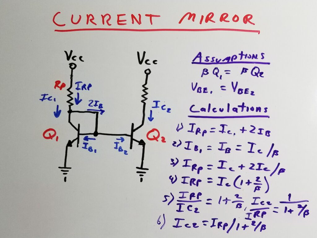
The current mirror is able to reproduce a current from one branch of a circuit to another. Referring to the image above, the current mirror functions as follows:
Here are some assumptions:
- The beta (gain of both transistors are the same)
- Vbe for both transistors are the same.
- Both transistors are operated in their linear (active) regions.
- Both transistors are maintained at the same temperature.
Calculations:
Given that Vbe and beta for both transistors is the same, the base current for each transistor must also be the same. Since the transistors are operated in their linear regions, the current through Rp is split between the collector and the branch feeding the two bases.
Thus, following the diagram above:
- Calculation for IRp, which is the program resistor current.
- Calculation for Q1 base current.
- IRp in terms of collector and base current.
- IRp after factoring out Ic.
- Ratio of Ic2/IRp (current transfer ratio).
- Ic2 (load current) in terms of IRp and beta.
The mirrored current through Q2 will stay constant regardless of load resistance or the voltage across the load (within design parameters). This is accomplished by the fact that the emitter-base junction of Q1 is maintained at approximately 0.7v. This maintains the base of Q2 at that same voltage. That causes Ib2 to stay constant regardless of the load resistance connected to the collector of Q2. The collector current is then dictated by Ib2 x beta. Since Ib2 is constant, the collector current also remains constant. So for high-gain transistors, the current through the target load is maintained at approximately the same as the reference current through Rprogram.
Summary
The current mirror replicates the current from one part of a circuit to another. This “remote” way of controlling/replicating current in another part of a circuit is commonly used in integrated circuits, amplifiers, and other circuits. It also provides a constant current source to the target load. Current mirrors can be constructed with bipolar junction transistors or field-effect transistors. The transistors’ characteristics must be closely matched for them to function both from a practical and formulaic standpoint. Maintaining the temperature of both transistors is also an important factor in a current mirror’s proper functionality. This is easy to do on an integrated circuit die, but can also be achieved mainly to an experimental degree, by connecting discrete transistor cases together.
Please see the matching video for this article on our Youtube Channel below.
For a better experience building breadboarded circuits, please see our page detailing the minimum recommended lab equipment for your electronics bench. Also, don’t forget to review the recommended safety tips to follow when building and testing breadboarded circuits.
Finally, for other interesting breadboarded circuits please visit the home page here or our YouTube channel here. SM
We are a participant in the Amazon Services LLC Associates Program, an affiliate advertising program designed to provide a means for us to earn fees by linking to Amazon.com and affiliated sites.
