The Classic Astable Multivibrator Oscillator
What is a Mulitvibrator?
A Multivibrator is an oscillator that consists of two amplifiers (transistors) and is cross-coupled by capacitors and resistors.
What does “Astable” mean?
“Astable” means “not stable. Thus an astable mulitvibrator is free-running. It spontaneously oscillates between states. It never reaches a stable (off or on) mode. This can be compared to a “monostable”, which can be prompted to change states momentarily, but will revert back to it’s “stable” off state, or a “bistable” mulitvibrator, where 2 distinct stable states can be prompted by applying potentials to specific parts of the circuit.
The Astable Multivibrator
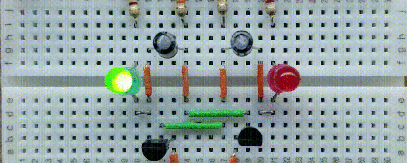
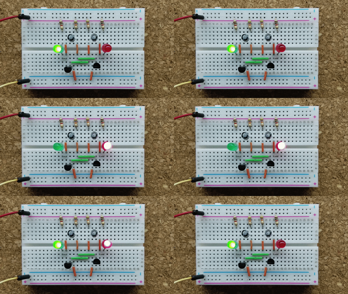
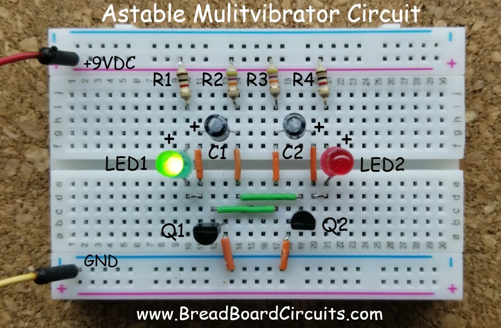
The Astable Mulitvibrator circuit in this example is a simple two-transistor oscillator that you can build with as few as 10 components. This circuit will alternately illuminate 2 LEDs as the mulitvibrator changes states. It consists of two NPN bipolar transistors and a few supporting components. When one transistor is turned “on”, the other one is turned “off”. The rate at which the transistors alternate states depends primarily on the values of certain resistors and capacitors in the circuit. A picture of the breadboarded circuit is shown below. It can be powered by either a 9V battery or a regulated power supply set at 9 volts DC.
Before building a breadboard, please review our safety procedures and recommendations page.
Supplies Needed
Supplies needed for this project:
- Minimum breadboarding equipment (see here)
- (2) 47k 1/4 watt resistors
- (2) 1k 1/4 watt resistors
- (2) 10uF 25v (or greater) electrolytic capacitors
- (2) 2n3904 transistors
- (2) Standard LEDs (colors of your choice)
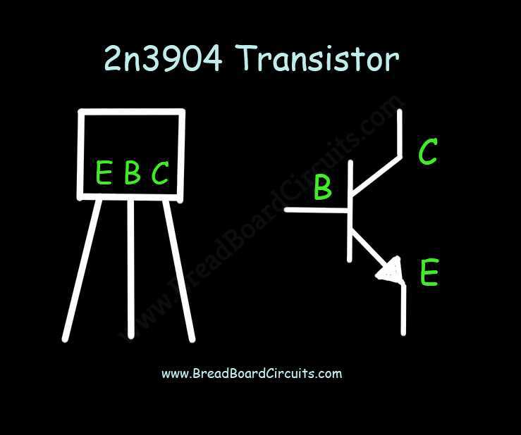
Construct the circuit exactly as shown on the breadboard, observing the orientation of the 2n3904 NPN transistors. Notice that Q1 is facing backward and Q2 is facing forward.
The 2N3904 Transistor Pinout
Below is both pinout (with the transistor facing forward) and the symbol for the 2n3094 transistor. “E” stands for Emitter, “B” stands for Base, and “C” stands for Collector.
Schematic of the Astable Multivibrator
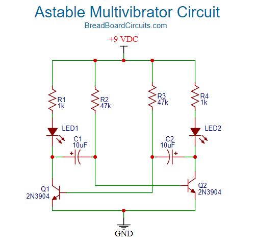
A schematic of the astable mulitvibrator circuit is shown below.
Theory of Operation
Before going through the sequence, let’s identify the purpose of the components. Q1 and Q2 are configured as “switches”, meaning that they will either be in their off (cutoff) or on (saturation) states. R1 and R4 simply limit the current through the transistors and consequently the LEDs. R2 and R3 together with C1 and C2 define the time constant that determines the oscillation frequency.
- When power is applied, one of the transistors (due to slight manufacturing differences between the two – let’s assume that it is Q1) begins in its “on” state. This means that the voltage across the emitter to the collector is close to zero volts. In this state, the current flows through R1 and LED1, causing LED1 to illuminate.
- That’s how the circuit starts. For the sake of an accurate analysis, lets now assume that the circuit has been oscillating for a while and we are back to the point where Q1 just turns on.
- Since the collector of Q1 is close to 0 volts, the positive side of capacitor C1 is also about 0 volts. Now, the right side of capacitor C1 will start out at -6.3 volts with respect to the left side. Why? Because it was quickly charged by Vcc via R1. It would have charged to 9 volts except there is a 2 volt drop across LED1 and a 0.7 volt drop across Q2’s base to emitter junction. This leaves a net voltage of 6.3 volts. That voltage is still there the moment Q1 turns on – because you can’t instantaneously change the voltage across a capacitor.
- Since the right side of capacitor C1 is -6.3 volts with respect to the left side, and the left side is now at a 0 volt potential, the right side with respect to ground is also -6.3 volts. This negative voltage forces transistor Q2 into it’s “off” state because the base to emitter junction is no longer forward biased. This also means that R2 has (Vcc – (-6.3)) or 9 + 6.3 volt (15.3 volts) difference across it. This voltage difference across R2, determines the initial charging current to C1.
- C1 now starts to discharge because to the positive current flow to its negative terminal via R2. Once the right side of C1 reaches 0 volts, it starts to negatively charge with respect to the left side. It only has to charge to 0.7 volts though, with respect to ground. The base of Q2 will limit it to that. Note that normally you don’t want to negatively charge an electrolytic capacitor. However, it is generally accepted that doing so at less than a volt is OK.
- The time it takes to bring the right side of C1 to 0.7 volts w/r to ground, depends on the time constant determined by the values of R1 and C1 (calculations later in this article).
- Once the right side of C1 reaches 0.7 volts w/r to ground, the base to emitter junction of Q2 becomes forward biased and Q2 turns on.
- LED2 illuminates because current is now flowing thorough R4 and the LED.
- Once Q2 and LED2 turns on, Q1 and LED1 turn off for the reasons described above. Q1 now has to wait until R3 charges the left side of C2 enough to turn Q1 back on. This cycle then continues indefinitely.
Design considerations
The most important design considerations are as follows:
- Determine Q1 and Q2 collector current. Since the two transistors are used as switches, they will be operated in their “on” (saturation) and “off” (cutoff) states. First, you want to ensure you stay below the maximum collector current of the transistor. For the 2n3904, Ic (max) is 200mA. Since we will be driving LEDs at under 10mA, this in no problem. The current through R1 equals that through the transistor’s collector. The current is determined by the voltage drop across R1. Thus, the supply voltage (9 volts) minus the LED voltage drop (2 volts) equals 7 volts. This means the collector current is 7 volts / 1000 ohms or 7mA – well below the transistor’s maximum collector current.
- Determine maximum value of base resistors (R2 and R3) to drive the transistors into saturation. We need to know the transistor’s gain in order to determine this. The gain or beta for the 2n3094 is typically around 200. Thus the minimum current at the base in order to drive the collector current at 7mA will be 7mA / 200 or 35uA. Since the voltage across the base resistors will be Vcc – 0.7 volts (8.3 volts), we can determine the resistor value that yields a 35 uA base current. Per Ohm’s law, R=V/I or R= (8.3 volts)/.000035 or 237k ohms. That is the base resistor value that will theoretically put the transistor into its active region – the region where there is a linear relationship between base current and collector current. However we want the transistor to operate in its saturation region, where it will behave like a ‘switch”. By using an overdrive factor of 5, we can push the transistor into saturation. This brings our base current to 35uA x 5 or 175uA. The new minimum resistor value is then 8.3/.000175 or 47k ohms. Note that here is also an absolute minimum resistor value. If you were to use 0 ohms, you would damage the base to emitter junction of the transistor. Thus, keeping the base resistor above 1k ohms is a good idea. Note also that the base resistors, along with capacitors C1 and C2 determine the circuit’s oscillation frequency.
- Determine needed frequency. This is explained in the next section below.
How to determine oscillation frequency
The frequency of the mulitvibrator is determined by the values of the base resistors and the capacitors. Assuming a 50% duty cycle, R2=R3 and C1=C2. This makes calculations much easier. It is the time constant (RC) that will determine how long it takes C1 and C2 to discharge to 0 volts and then continue on and negatively charge to 0.7 volts. The output frequency is determined by time it takes for each side of the circuit to accomplish this, multiplied by two. For the mulitvibrator circuit in this article, the time for transistor Q1 to flip to its opposite state is 0.693 x R2 x C1. Since we have a 50% duty cycle (symmetrical circuit), the total time period is 1.385 x R x C. Frequency is the inverse of this, so that would be 1/1.386 (R x C) or 0.72 / (R x C). Hence for our example, the frequency will be 0.72/47k x 0.000010 = 1.5 Hz.
Suppose you wanted a frequency of 10Hz? Choose which component to change in value (R or C). Suppose you wanted to leave the 10uF capacitor in place and only reduce the resistor value. Thus, a simple rearranging of the equation yields R = 0.72/(f x C) or 0.72 / (10Hz x .000010) = 7200 ohms. Thus, you would change R2 and R3 to 7200 ohms. Note that this value falls within the maximum and minimum values as determined by the “Design Considerations” section.
What can this circuit be used for?
A mulitvibrator is an oscillator. Oscillators have many uses. Here are just a few of many possibilities:
- A simple flasher
- A pre-driver for a higher current or higher voltage flasher.
- A tone generator
- A clock signal for digital circuits
- A frequency divider (when an external square wave is used to trigger one side of the circuit)
- A timer
- A pulse width modulator
Modifying the circuit to output a “clean” square wave.
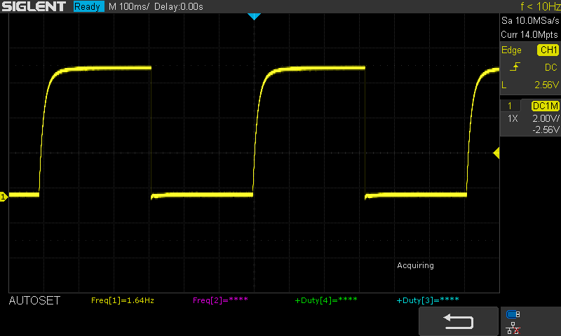
The classic astable mulitvibrator circuit in this article produces an approximate square wave. The leading edge, however, is rounded, due to the time it takes C1 to charge back up once Q1 “opens up” or turns off. There are improvements to the circuit that can sharpen up the square wave output. A clean square wave is important for applications such as clocking digital circuits, driving high current drivers, or likewise as a PWM generator. One reason is because when driving a high-current output device such as a BJT or Field Effect Transistor, you’ll want that transistor to spend all of its time either “off” or “on”, and not in between. Driving the transistor otherwise (with a rounded waveform and resulting slow rise time), will cause the transistor to dissipate excess and unnecessary power and heat. This is because the the driver transistor or device spends too much time acting as an amplifier (which dissipates power), instead of a switch (which ideally dissipates no power). The output waveform at the collector of Q2 for the above circuit is shown below. Notice the slow leading edge rise and sharp trailing edge drop. You’ll really want the leading edge to look just like the trailing edge – for a clean and symmetrical square wave. Simply adding two transistors and two resistors to solve this problem. This is detailed in the article “Improved Astable Multivibrator Circuit with Clean Square Wave“.
For a better experience building breadboarded circuits, please see our page detailing the minimum recommended lab equipment for your electronics bench. Also, don’t forget to review the recommended safety procedures to follow when building and testing breadboarded circuits.
Finally, for other interesting breadboarded circuits please visit the home page here or our YouTube channel here.
We are a participant in the Amazon Services LLC Associates Program, an affiliate advertising program designed to provide a means for us to earn fees by linking to Amazon.com and affiliated sites.
